Introduction to the NSB Di2
Between 1964 and 1983 the NSB bought 54 switching locomotives type Di2. The first 6 were built by MaK in Germany (as MaK 575C), all the other by Thune in Oslo. The first 8 locomotives had MaK engines (MS301), the others had BMV engines (BMV LT6). They were in service until 1999. The Di2.833 is preserved in the Norwegian Railway Museum in the original green color.
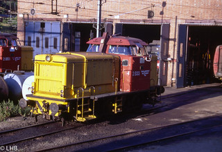 Di2.833 - Oslo - July 10, 1995
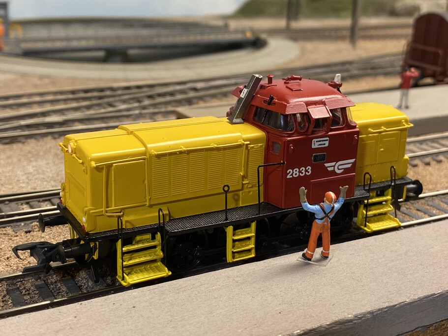
 NMJ Di2.833
NMJ had a small serie of the Di2 made by DHJ in the early 2000's. This model uses the Roco V60 drive, which is a good running drive.
I installed a Lenz LE0521W decoder shortly after I bought the model. After I was able to install a sound decoder in the Di5, which is using the same drive train, I thought of installed sound in this Di2 as well. But what sound to use? I browsed the Loksound 5 catalog and I found a MaK 650D project with a MS301CK engine. This is as close I can get to the Di2 (the first 8 had a MS301 engine).
DCC Sound Installation
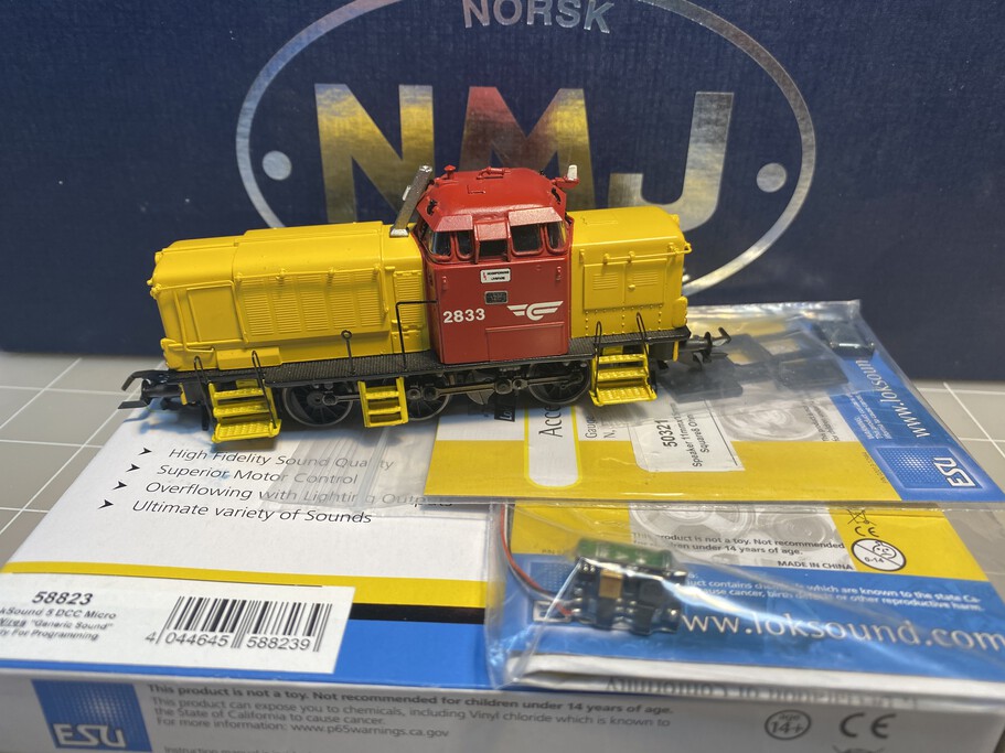
The NMJ Di2 and the ESU parts for the installation:
- 50321 - Small speaker kit
- 54671 - Power Pack
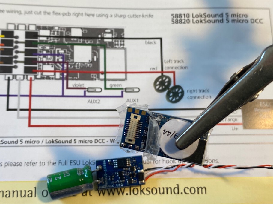
- 58823 - Loksound 5 Micro DCC (with wires)
- S0343 - Loksound 5 MaK 650D sound file
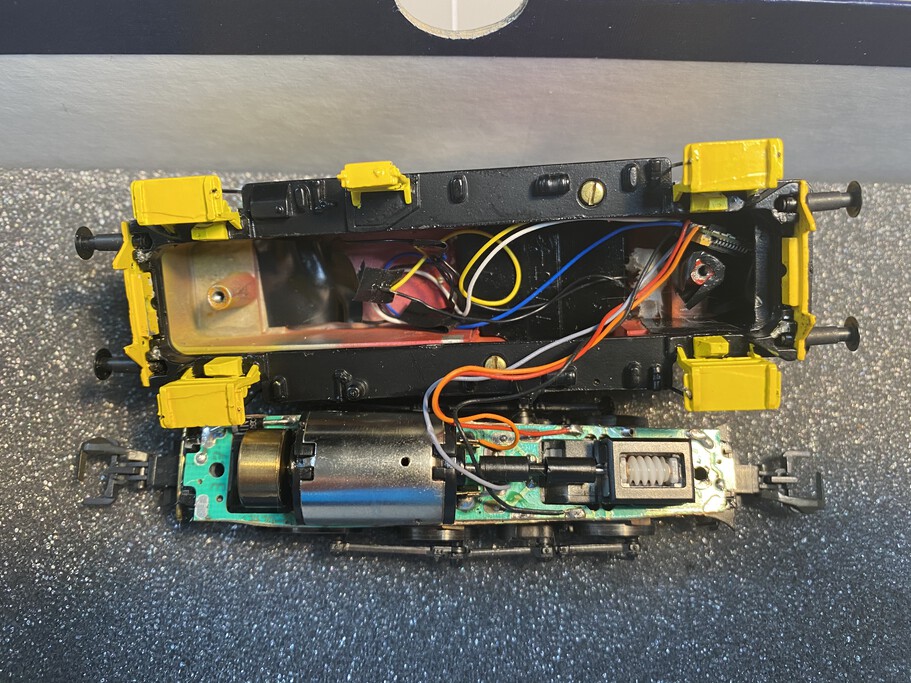
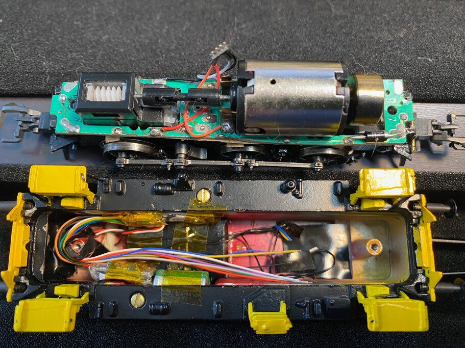
Opening the locomotives shows the old LE0521W install. The small decoder was tucked way in the nose. The drive train is from a Roco V60.
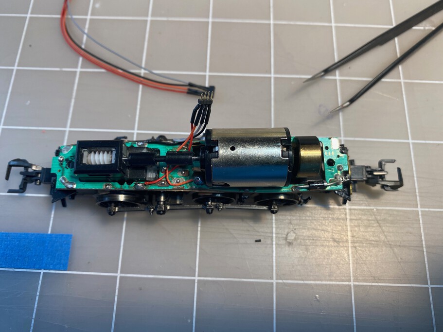
As all the install components will be installed in the body, I wanted a clean connection with drive train and therefore I installed a small 4 pole connector with the correct wire colors (black/red for the power; grey/orange for the motor leads).
A key component of the install the ESU Power Pack. The three wires need to be directly connected to the decoder. Therefore the plastic blister around the decoder is carefully removed. In this picture I already added some solder tin to the three wire connection points. The wire diagram is the back and the Power Pack is ready as well.
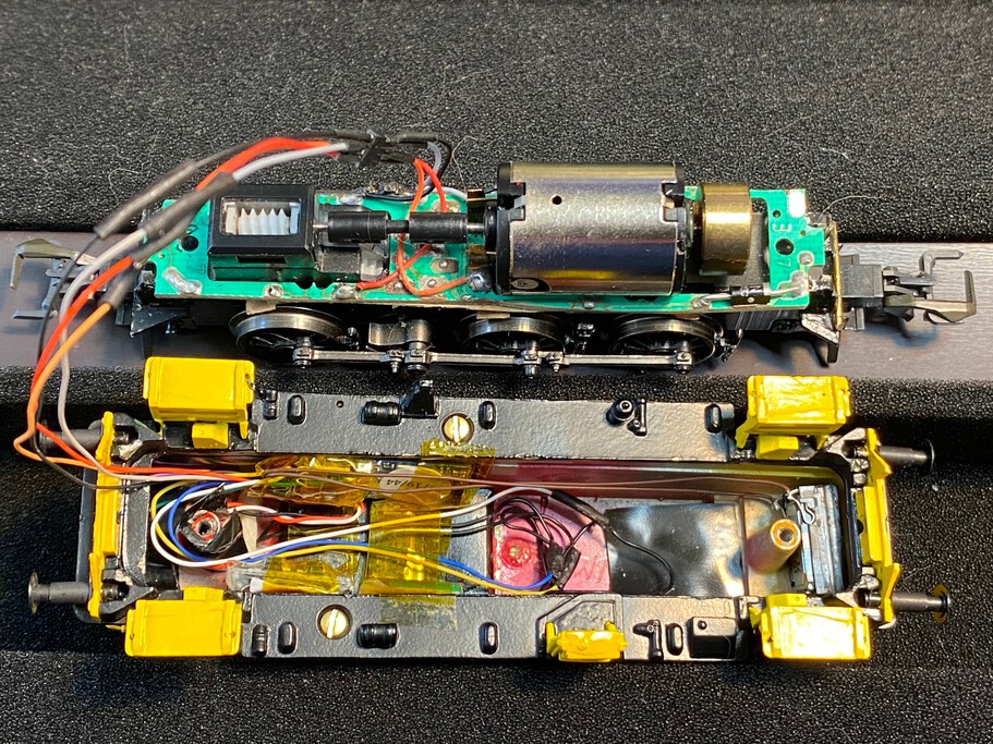
Initial positioning of the components. As the cab is wider than the body, there is space in cab walls to place the decoder (upper part of photo) and the power pack (lower part of the photo). The wires are moved along the mounting screw column. Part of the old light wiring is still not removed. The speaker will be placed in the front of the locomoive (far right part of the photo).
Installation complete, just before the body is put back on the drive train. The speaker is glued, with a small part of the baffle box, to the front of the body,. The light wires are now visible with proper shrink wrap around the wire leads.
A quick test showed that the ESU Power Pack wasn't working, even though all the programming was done correctly. I had to take the locomotive apart and then it showed that the black wire had snapped off the Power Pack PCB board. After soldering that back on the board, the Power Pack was functioning correctly.
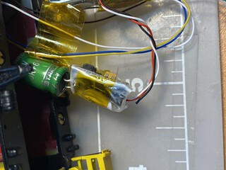 Black wire snapped off
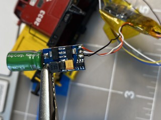 Soldering it back
Created: 2020-05-09. Update: 2020-05-09