Installation
In early 2003 I did a DCC conversion of a Roco El16 and I described all the steps on this page. Fast forward to 2016 and there are
better ways to do this conversion. See El16 with PLUX decoder for a new DCC conversion that I did in May 2016. This page is kept for reference.
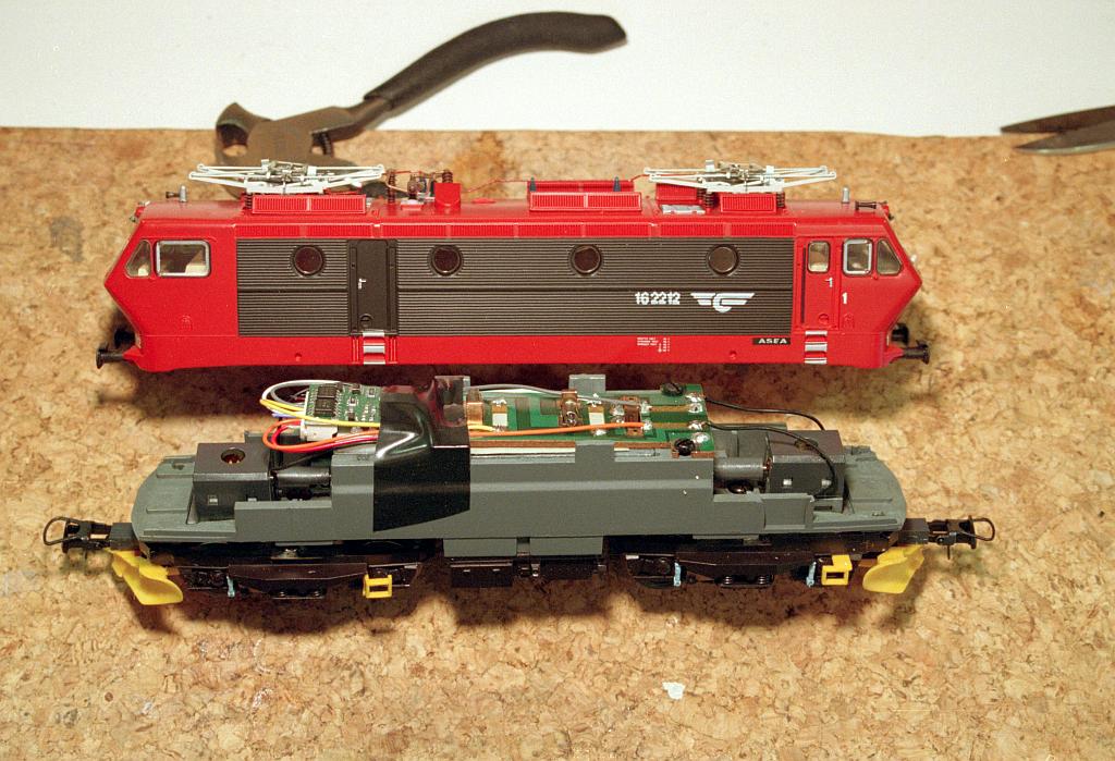
Roco makes a very nice model of the Norwegian El16 class. The first run, in
the red and black 'ny design' colours, doesn't have the NEM interface so
it will take some effort to install a DCC decoder. The later run in the
old brown 'gammel design' colours does have the NEM interface so that makes
it a lot easier.
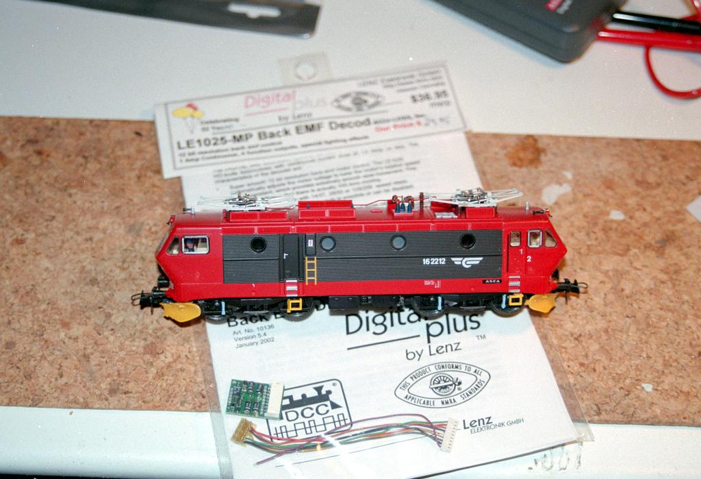
The Lenz LE1025 decoder is a great decoder that has one of the best
BEMF control on the market. Tony's Train Xchange does have a great
article
that compares this decoder with other BEMF decoders.
The following pictures shows a way of installing a LE1025 in the Roco
El16
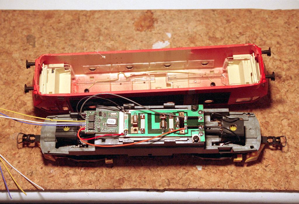
Remove the shell, by widening the body a little bit. The printed circuit
board is clearly visible. The Lenz decoder is shown in the location it will
be installed eventually. Currently this space is occupied by a switch that
allows to change the power pickup from track to overhead wire.
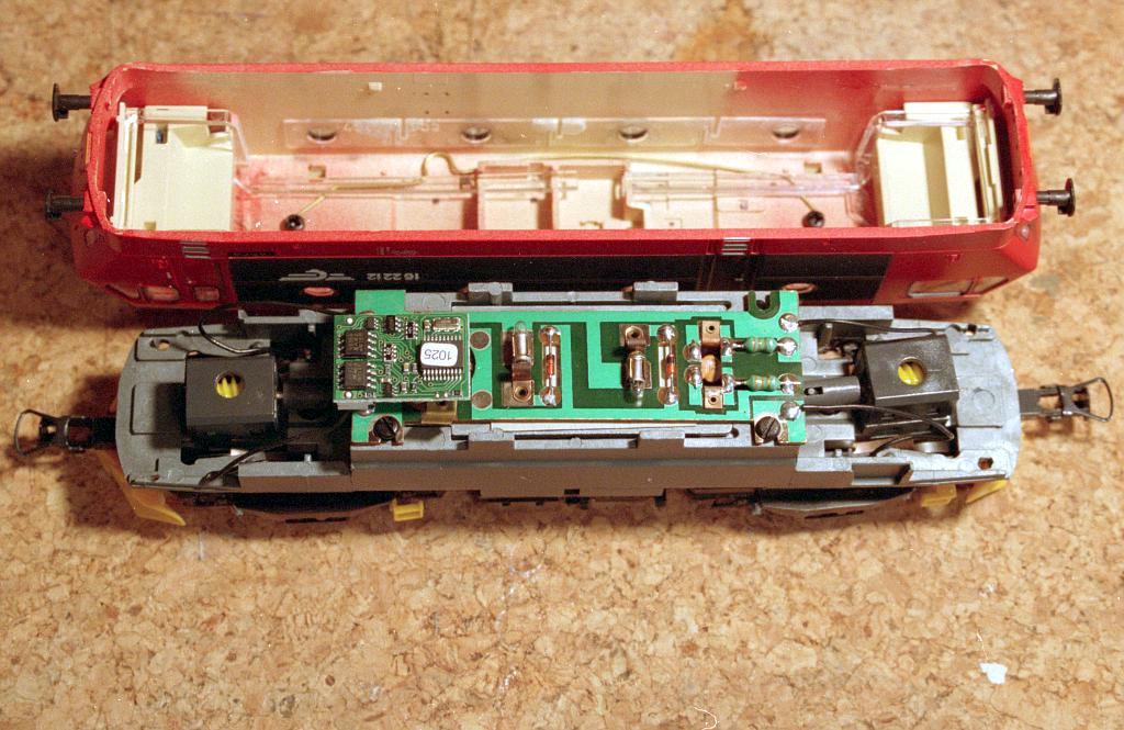
The resistors, capacitor and diodes need to be removed. This picture shows
the printed circuit board after the removal of these components. Compare
with the previous picture for their location. The capacitor sits
underneath the board between the copper strips that attach to the motor.
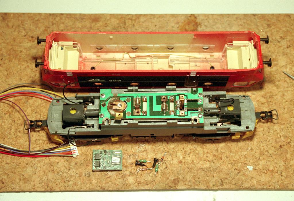
The printed circuit board is removed and with a small saw the left part
that holds the switch is removed.
The switch is gone and in its place sits a piece of white double sided
tape. The wires from the bogies are attached again. This requires scrapping
off a little bit of isolation of the circuit board.
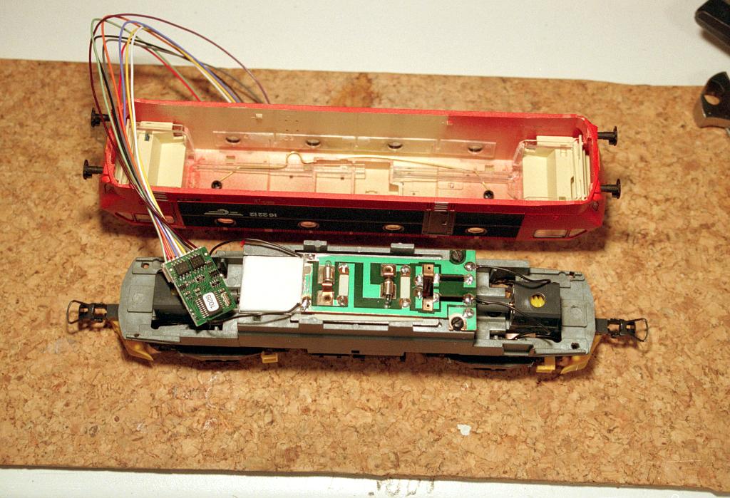
The decoder is put into place and the red and black decoder wires are
soldered to the track pickup locations on the circuit board.
The orange and grey wires are soldered to the motor pickup locations, where
the capacitor used to sit.
After this is done put the locomotive on the track and select number '3'.
If everything is alright the locomotive should run. Please note the
direction, because we need this for connecting the function wires.
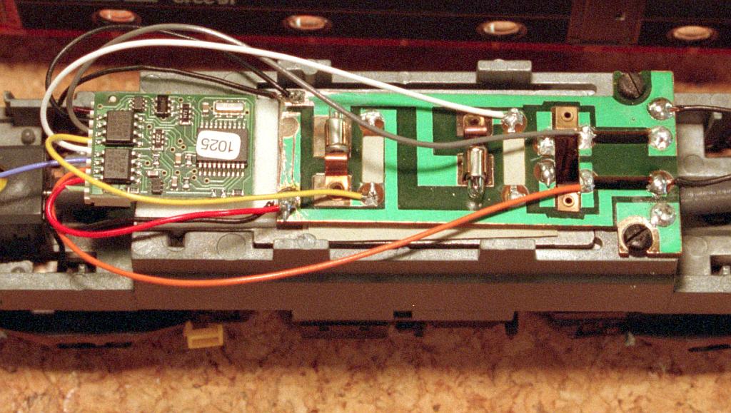
If the locomotive doesn't run check the wiring again and compare it with
the next picture which has a more closeup view of the decoder, printed
circuit board and the wires.
The white wire is for the front lights and connect it to the light that is
'front'. The yellow wire goes to the rear. In this example the blue common
wire is not used because the lights are connected to one of the pickup
wires on the print circuit board. In this configuarion the lights will get
half the voltage they used to get. If you prefer to use the blue wire then
you have to isolate both lights from the pickup wire on the printed circuit
board.
A piece of electrical tape is used to secure the wires and the decoder and
the shell/body can be put back on the frame. Make sure that 'cab 1' is
sitting in the front location.
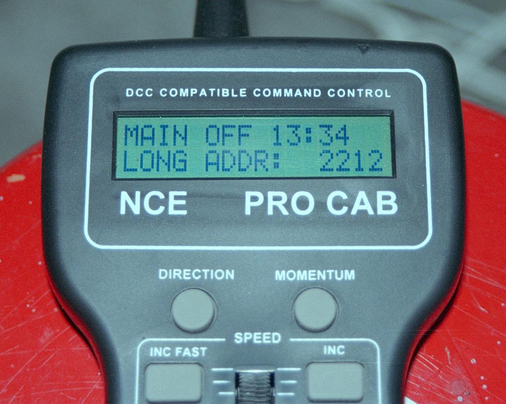
The last step is to the program track to program a new address. I use four
digit addressing and normally use the last four digits from a Norwegian
locomotive number for the address. So in this case the El16.2212 will get
address 2212.